Our student Daphné Tapia on her internship at Alcatel Submarine Network focussing on GIS support tools for submarine cable routing and project planning
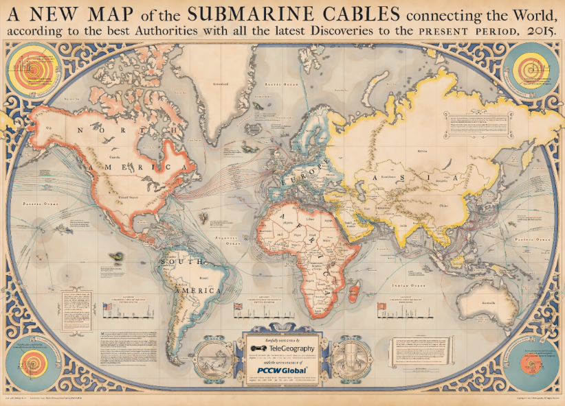
Who has ever thought that our internet connection, phone calls and favorite TV show on Netflix were dependent on cables laying under the sea? Contrary to the common thought, more than 90% of our communications depends on submarine cables, not on satellites. For what reasons you ask?
Fiber optic submarine cables have an unsurpassed transmission capacity of tens of Terabits whereas satellites have a capacity of few Mega Bits. Satellite in orbit also have delay problems: back and forth the signal must travel around 200 000km. Delay can reach one second, which is unbearable for some systems. As the cable lay directly on the Earth, no delays are faced. Last, cables have a lifespan of 25 years against less than 10 years for a satellite. Satellite transmission can suffer interferences whereas cables lying bellow 8000 meters of water do not.
The first submarine communications cables laid beginning in the 1850s carried telegraphy traffic, establishing the first instant telecommunications links between continents, such as the first transatlantic telegraph cable which became operational on 16 August 1858. Modern cables use optical fiber technology to carry digital data, which includes telephone, Internet and private data traffic.
The team I was working with works, among other subjects, on innovative methods to define the initial cable route on the sea bottom: in fact, the route that submarine cable will follow is carefully studied and the path accurately selected to minimize the length, but also to avoid risky or difficult areas e.g.
- Highly seismic areas, volcanos
- Chemical and explosive disposal areas
- Areas with presence of UXO
- Firing exercise areas
- Anchoring areas
- Fishing areas
- Sliding seabed, submarine canyons
- River fans (turbidity)
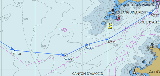
Some specific bathymetric databases need to be considered: What temperature is the water? How deep should the cable go? Where are the currents coming from? What is the soil composition? What is the degree of the slope? Nothing can be left to chance. The different cable types are chosen relatively to all these questions to make sure the cable can resist natural/human threats and is well adapted to its environment.

There are essentially two ways to install a cable: it can be laid on the sea bottom or buried deeply into the sea bottom to be more protected. Huge ploughs are used to bury the cable and Remote Operated Vehicle (ROV) are used to inspect and finalize the cable burial where needed.

The ROV is connected to the vessel and the personnel on board pilots the machine. ROVs can go down to 2500m. Cables are buried where there is a risk for them. For instance, ship anchors or fishing activities are potential threats near the surface. The deeper the cable is installed, the safer it is submarine cables can typically be installed down to 8000m although most of the oceanic water are less deep than that.
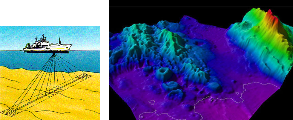
Different techniques are used to map the seafloor, especially sound. Sonar systems function like an antenna sending out sonar signals (sound waves) and receiving return echoes. Then the electrical energy is converted into sound waves and vice versa. Only the use of sound sonar has permitted large-scale, high-resolution sea floor measurement. 10 to 15% of the ocean has yet been map with high resolution. However, a specific sea bottom survey is performed prior to the installation of any submarine cable system, along the planned cable route, to have a precise cartography of the site.
The most important component of the cable is the optical fiber. A fiber-optic cable comprises multiple pairs of fibers. Each pair has one fiber for each direction of transmission. Each cable system includes several optical amplifiers improve the signal/noise ratio.
WDM (wavelength Division Multiplexing) technology allows to use signals of different wavelength (color) to transport several different communications in each fiber pair without mixing them.
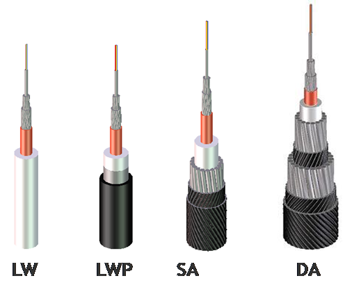
A typical deep water submarine cable is only 17 mm in diameter: nevertheless, several layers of various materials surround optical fibers: these are used to protect the fibers from external aggressions, but also to transport the necessary electrical energy for the optical amplifiers along the submerged line.
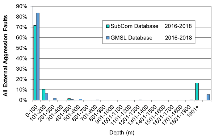
Close to the shore, where the risk of aggression is much higher, the cable is further protected by various layers of steel wires (armouring). In fact, most of the accident happen in water depths down to two hundred meters: at deeper water depths accidents are very rare.
Submarine cable systems are often very long, sometimes more than 10 000 km: their production and installation require huge investments and a considerable know how. That’s probably why only a few companies in the world master the whole set of the required technologies.
The company I was interning with are using several marine mapping software to determine cable path. The objective of my internship was to study the possibility to automatize some parts of this activity by using a GIS. I helped the marine team in developing Construction Project Management while combining platforms such as Microsoft Project (MP) and GIS. Tools like MP are lacking spatial attributes. That is why it is necessary to complete this with a GIS software. GIS integrated project management will be very helpful to create geo-spatial information useful for managing time and cost involved in the project.
During this internship, we used the Cost Distance Analysis Tool from different software to figure out the shortest and cheapest path the cable should follow. To do so, we gave weight to some parameters: should the slope be more important (heavier) than the seabed components? The research we did to find the appropriate weight is time consuming, because we had to try all kind of values scale to see which one works the best. We could then draw comparison between our different results to see what route could eventually be selected. For now, the question remains open: automatic routing or traditional hand-made drawn roads for tomorrow’s cables laying?
Daphné Tapia, 8th intake


